- TOP
- Basic Knowledge of CAE Analysis
- Part 1 What is CAE -FEM-?
Series: Fundamentals of CAE Analysis for Plastic Product Design
Part 1 What is CAE -FEM-?
We will introduce basic knowledge of CAE and the key points of the finite-element method (FEM), which is commonly used in analysis.
Update date:
2022.07.21
|Release date:
2022.07.07
Contents
| 1. What is CAE? |
| 2. Prerequisites for exploiting the full power of CAE |
| 3. What is the finite-element method(FEM)? |
| 4. Summary |
| Experience Your First Structural (Stress) Analysis Simulation |
What is CAE?
In recent years, CAE analysis has become an indispensable tool for mechanical design. In short, CAE—which stands for Computer-Aided Engineering— is a technique for using computers to make better design decisions during the product development process. It does so by helping to evaluate the suitability of design candidates and by giving hints on how to improve them.
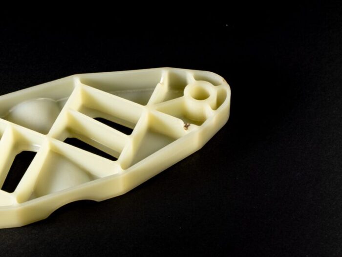
Before the use of computers in manufacturing, fine details regarding the shapes and structures of products could only be investigated by constructing actual prototypes. Round after round of prototypes had to be constructed and tested for durability and other properties before mass production could begin—a process that was both expensive and time-consuming.
It was against this backdrop that CAE was originally developed in the U.S., with the first commercial software packages appearing in the 1970s and the field developing rapidly as the capabilities of computers grew throughout the 1980s and beyond. Today, CAE techniques are used from the earliest stages of the design and development process—to construct mathematical and physical models, to predict product specifications, performance, and quality via software tools, and to optimize product designs.
Although CAE techniques were originally used to design metal-based products such as rockets and airplanes, today these methods have become essential tools for developing plastic products as well. This series begins with a general introduction to CAE, then goes on to cover more specialized topics: differences in the properties of various plastics, manufacturing process simulations, and structural-analysis simulations for plastic products.
■ How are CAE tools used?
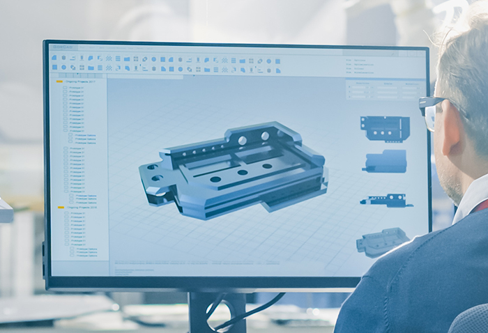
Nowadays, the whole product design and development process is digitalized, which is described by the terms CAD and CAM. This allows for a seamless integration of CAE.
CAD (Computer-Aided Design) systems help to manage the process of product design. The 3D CAD tools primarily used today allow the design of free-form surfaces–a significant improvement over the previous generation of 2D CAD tools, which lacked sufficient degrees of freedom to handle such complexity. By making use of 3D CAD data at factory production lines, it has even become possible to design product molds themselves via CAD techniques.
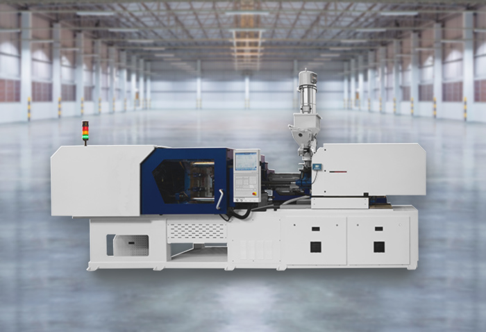
CAM (Computer-Aided Manufacturing) systems prepare the information needed to manufacture products–such as control data for NC machine tools. Numerical Control (NC) machine tools are computer-driven instruments for automated processing of products. Whereas conventional machining involved human machinists manually turning dials and pulling levers to make cuts and drill holes, NC tools may be programmed with numerical control data to automate the position and dimensions of cuts, and every other aspect of the fabrication process.
In short, design data prepared using CAD techniques may be converted into numerical control data for CAM systems to enable automated operation of machine tools. CAD and CAM tools are often packaged together in software products known as CAD/CAM systems. The enormous reduction in conventional analog processing steps has enabled higher-precision engineering and more efficient operating processes.
A typical design/development flow might consist of using CAD tools to design products and molds, applying CAE analysis to revise design data and eliminate product-manufacturing problems, then sending the data to CAM-based NC machine tools to fabricate products.
The use of CAE allows product design candidates to be evaluated using CAD-generated design data—before anything is fabricated. Whereas product design once demanded a cumbersome trial-and-error cycle—involving hand-tuning of fabricated prototypes and depending on the experience and intuition of expert craftsmen—today the entire process can be analyzed via computer simulations. The trial-and-error cycles are not only sped up, but the CAE analysis also allows for a more detailed understanding of the results than it is usually possible with pure testing.
■ What is possible with CAE?
But what sorts of analysis are possible with CAE? Today’s CAE tools span a vast range of application domains, each addressed by a host of customized software packages. More specifically, CAE is used in all sectors of modern technology—from mechanical products to electrical and electronic systems, architectural designs, chemical processes, medical procedures, and more—as well as in the study of natural phenomena, enriching many aspects of our daily lives.
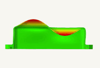
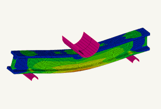
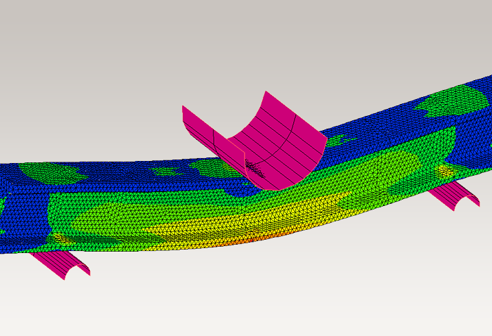
For example, in mechanical design and related fields, CAE-based structural analysis is used to ensure that moving parts of products do not interfere with other components–without the need to fabricate prototypes.
 Fig. 1 Multibody dynamic analysis result
Source: Model in the video of “Contact Analysis”, “Disruption and Damage Analysis”(Viewed February 26, 2021).https://www.mscsoftware.com/product/marc
*Model in the video of “Contact Analysis”, “Disruption and Damage Analysis”(Viewed February 26, 2021).
https://www.mscsoftware.com/product/marc
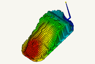
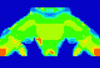
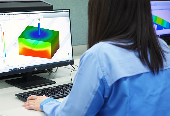
Even within the particular subfield of molding-based manufacturing, there exist specialized commercial software packages for plastic injection molding, metal casting, die casting, press dies, and other specific sectors. The CAE technique most commonly used for plastic injection molding is fluid analysis , which allows designers to simulate whether or not plastic materials can be properly injected into molds.
 Figure 2 State of resin filling obtained by injection molding analysis
■ An essential tool for modern manufacturing
Using CAE tools to evaluate CAD-generated design data reduces prototyping iterations, dramatically shrinking development lead times and reducing costs. As software advances and computers grow more powerful and less expensive, CAD-equipped designers can use CAE tools to design and analyze products themselves—without depending on expert engineers to perform specialized analyses. The advent of 3D CAD/CAM and CAE systems has had a transformative effect on the structure of the manufacturing industry.
In today’s world, amidst ever-shrinking development times and growing demand for cost reduction, it is safe to say that CAE analysis has become an absolutely indispensable tool for modern manufacturing.


Prerequisites for exploiting the full power of CAE
As powerful and convenient as CAE techniques can be, mastering the art of modern CAE requires more than simply learning a few software tools. One might hope that the results of a CAE analysis could be so simple as to be immediately understandable by anyone, regardless of their background or expertise—but this is far from the case. Instead, the ability to accurately interpret CAE results and incorporate them into designs requires not only knowledge of how to use software but also a grounding in the basic engineering discipline of material mechanics and a thorough understanding of basic CAE techniques.
■ Fundamentals of material mechanics
Material mechanics is a discipline that investigates how structural components deform and rupture under various types of applied forces. In material mechanics, forces are represented by vectors. While forces (like gravity) will always act on a body, they are balanced for a structural body that is at rest.
The forces acting on structural components include both external forces (or loads) and internal forcesthat arise within components to resist external forces. Types of external forces include tensile loads, compressive loads, shear loads, bending loads, and torsion loads. Internal forces are characterized using the notions of stress and strain. Stress is defined as internal force per unit surface area. Because the internal forces acting on bodies are invisible, computations are carried out by conceptually considering cross-sectional slices through bodies and using the notions of virtual cross sections and cross-sectional coefficients. Considering forces per unit surface area allows to separate the influence of the material properties from the influence of the geometry. Therefore, if the material properties are known, a designer can focus solely on the part geometry, when developing a part.
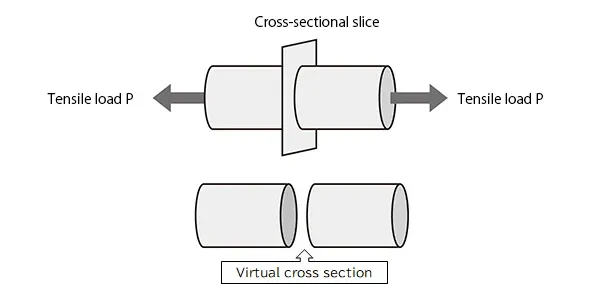 Fig. 3 virtual cross section required to calculate stress
As an example, consider a rod with a circular cross section that is pulled from both left and right to produce a tensile load P of 100 N. Assuming a virtual cross section with a cross-sectional area 20 mm2, the stress σ is given by
σ=100/20 N/mm2=5 N/mm2=5MPa
σ=100/20 N/mm2=5 N/mm2=5MPa
i.e., the stress arising within the rod is σ=5 N/mm 2. As it turns out to have the same unit as pressure, strain is often also expressed in MPa .
Strain measures the extent to which materials distort in shape. Because strain can be measured numerically using a strain gauge (nowadays also by measuring the sample’s distortion in a video (DIC)), strain is commonly used for laboratory characterization of actual bodies, while stress is commonly used in the design process.。
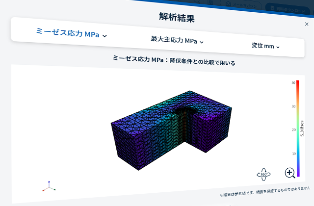
Although material-mechanics computations can be carried out by hand for simple bodies, most real-world bodies have complex structures that are extremely difficult to analyze via manual computation. For example, the stress on the body shown at the left in the figure below is not difficult to determine by hand. However, the addition of even just a single hole to the body, as shown at the right, makes material-mechanics calculations extremely complicated due to the concentration of stress in the vicinity of the hole.
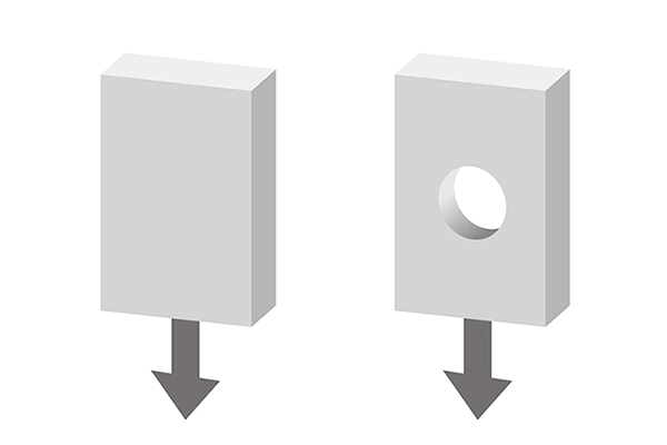 Fig. 4 An example where stress can be easily calculated by hand (left) and an example where it is not possible (right)
For such cases, we use CAE tools. CAE techniques allow even complex-shaped bodies to be analyzed with ease.
■The three main approaches to CAE
CAE analyses proceed by using various techniques to subdivide bodies and structures into small units that are easy to analyze, yielding coupled systems of equations that may be solved numerically. There are three primary CAE techniques in common use today to simulate viscous fluids and solid matter: the finite-difference method, the boundary-element method, and the finite-element method.
(1) The Finite-Difference Method (FDM)is the oldest of the analytical methods still in use today. This technique, widely used for fluid analysis, proceeds by discretizing the objects of interest on an orthogonal lattice known as a finite-difference grid. A drawback of FDM techniques is that they are poorly suited to the analysis of bodies with curved boundaries or other complicated boundary conditions.
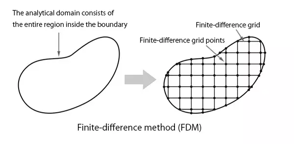 Figure 5 Finite difference method (FDM)
(2) The boundary-element method (BEM) is a technique in which only the boundaries of material regions are discretized for computational analysis. This approach is commonly used to study configurations of electromagnetic fields.
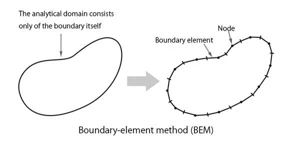 Fig. 6 Boundary element method (BEM)
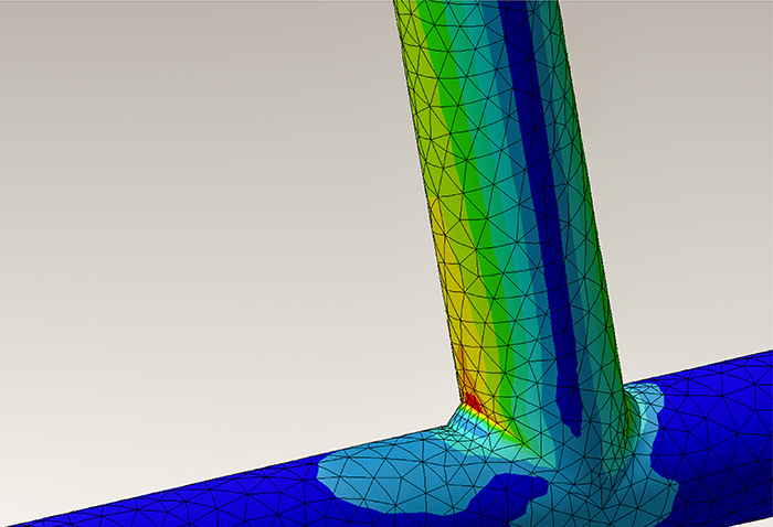
(3) The finite-element method (FEM) is the most commonly used analytical approach today. In this approach, the bodies of interest are subdivided into collections of simple shapes such as triangles or rectangles. Because this approach is capable of modeling not only 2D but also 3D systems, it is widely used for purposes such as structural analysis, thermal analysis, stress analysis, and vibrational analysis.
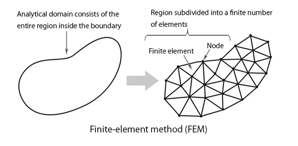 Fig. 7 the finite-element method (FEM)


What is the finite-element method(FEM)?
■ FEM techniques were first used in the structural design of airplanes
The finite-element method was originally developed in the 1950s to analyze the strength of airfoil structures in the design of airplanes. With the advent of jet engines, airplane structures became exceedingly complex, thereby requiring calculation of structural strength with sufficient accuracy.
This was also around the time that general-purpose digital computers became widely available, enabling numerical computations to be carried out rapidly.
■ The basic philosophy of the finite-element method
The finite-element method proceeds by subdividing bodies and material regions into collections of simple shapes such as triangles and rectangles; such a subdivision is known as mesh discretization. Each individual component in a mesh is known as an element, and each of the vertices comprising the elements is known as a node.
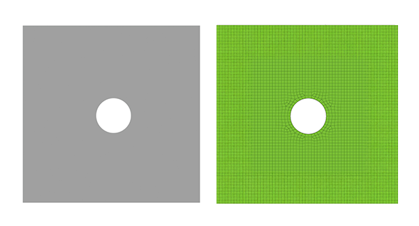 Fig. 8 An example of mesh division of a 2D model
In three-dimensional analyses, bodies are subdivided into three-dimensional (solid) elements.
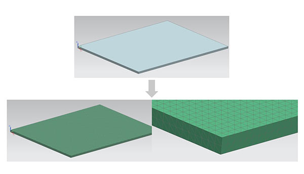 Fig. 9 Example of mesh division of 3D model
Considering external forces (such as gravity or pressure) acting on each element yields equations for that element; because each element is connected to multiple nodes, the external forces acting on each individual element are transmitted via the nodes to its neighbours and from there to the entire structure. Assembling the equations for all elements yields a simultaneous system of linear equations, which may be solved to obtain the displacement or stress for each element. In short, the finite-element method solves difficult problems by decomposing them into a set of simple equations and solving those. Of course, when the method is used to analyze complicated problems, the number of coupled equations can be quite large—in the thousands or even millions—requiring computer-based matrix computations to obtain solutions.
■ Key features of the finite-element method(FEM)
The nodes assigned to the vertices of each element are known as first-order elements. In some cases nodes are also assigned to intermediate points within shapes, yielding second-order elements. The accuracy of calculations may be improved by increasing the number of nodes.
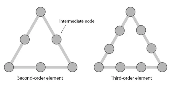 Fig.10 Distinguishing finite elements of different orders
Alternatively, the accuracy may also be improved by refining the mesh discretization to increase the number of elements in the model. Either of these improvements causes the approximate finite-element solution to approach the exact theoretical solution of the problem—at the expense of requiring more computation time. On the other hand, no matter how minutely we refine our model it will, in general, be impossible to reproduce the actual shapes of complex bodies. Ultimately, CAE analysis is nothing more than a technique for converting complicated problems into computationally tractable models to yield approximate solutions.
Needless to say, real-world design processes must be completed in a finite amount of time. Because finite-element analysis and other CAE techniques are used to shorten development lead times, the accuracy requirements to be imposed on a given analysis must be chosen appropriately for the purpose of the analysis and the context in which it is carried out.
Summary
The introduction of 3D CAD/CAM and CAE analyses has transformed the world of product design and manufacturing. Today these techniques are used not only for airplanes and automobiles, but also for plastic products and a wide range of other purposes; they have, without question, become indispensable tools for modern manufacturing.
At the same time, taking full advantage of these powerful tools requires more than simply purchasing computers and installing software: exploiting the full potential of CAE techniques requires a thorough understanding of their basic principles, theoretical underpinnings, and practical implementations.
Next part: "Key points of Plastic CAE -Difference from Metal-".
◆Please also make use of Beam Calculator which is useful for checking the validity of CAE analysis results and understanding basic deformation and stress.


For more information about CAE, please contact us.
CAE Download Slides

CAE Application Case Study

CAE Services
Others


Related Information