- TOP
- Fundamentals of CAE
- Part 12: Topology optimization for Design
Series: Fundamentals of CAE Analysis for Plastic Product Design
Part 12 Topology optimization for Design
Topology optimization is an innovative technology that accelerates the design process, eliminates waste, and derives optimal shapes. This Topology optimization introduces the basic concepts and methods of Topology optimization for those who have not yet used it.
2025.05.07
Contents
Introduction
For many designers, it is a huge challenge to improve the functionality and performance of a product while also meeting constraints such as cost and manufacturability. Structural optimal is one method for solving this problem.
The concept of optimal the design of structures is said to have been around since the 1980s, and after the basic theories were studied in academic circles, it was applied in industry, and the computing power of computers improved, and in recent years it has come to be used in a wide range of industrial fields.
Structural Optimization Methods
There are three main methods for optimal a structure: size optimal, shape optimal, and Topology optimization.
Dimensional optimal is a technique for optimal dimensions by using arbitrary dimensions, such as the length and thickness of a component, as variables, as shown in Fig. 1(a).
Shape optimal is a technique for optimal the shape of a part by using the external shape as a variable, as shown in Fig. 1(b).
These techniques are suitable for use when you want to fine-tune the external shape without changing the basic structure. However, these techniques cannot dramatically change the structural form, so the structure may not be truly optimal. Therefore, Topology optimization, shown in Fig. 1(c), is a technique that allows for optimal with a higher degree of freedom.
In this article, I would like to introduce Topology optimization, a type of structural optimal.
 Fig. 1 Structural optimal method
What is Topology optimization?
Topology optimization is a structural optimal method that calculates how to arrange materials in the space to be designed to create optimal structure.
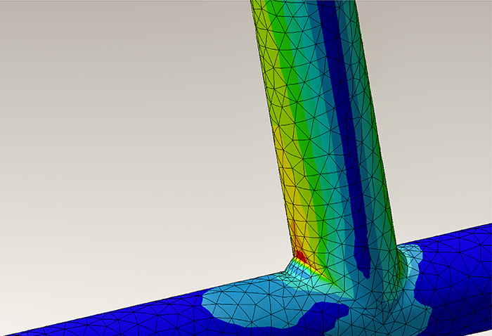
For example, consider the case where both ends are supported and a load is applied to the bottom surface, as shown on the left in Fig. 2. In Topology optimization, the area in which materials can be placed, called the design space, in other words the range to be optimal, is divided into small elements, and optimal calculations are performed while adjusting the material density for each element.
An example of the analysis results after Topology optimization is shown on the right in Fig. 2. The color represents the material density, and by placing material in the high density distribution areas shown in red, it is possible to create a structure that ensures strength more efficiently.
Topology optimization allows for shape optimal with such a high degree of freedom that it has the great advantage of being able to derive optimal solutions that would be difficult to arrive at using human intuition alone.
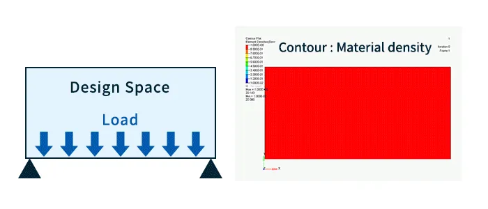 Fig. 2 Topology optimization results (Contour : Material density)
Information required for Topology optimization
Topology optimization requires the following information:
- Design space
- Various input data (physical properties, load conditions, boundary conditions, etc.)
- Objective function
- Constraints
The first design space is the area where the material of the part you want to optimal can be placed. Set the area where the target design part can be placed within design constraints such as interference with other parts. The larger this area is, the more freedom you can have in optimal design. It is also possible to define areas where material must be placed as specifications as non-design spaces. For example, if you want to fasten a part with a bolt, you can define the area near the bolt to fix the shape as a non-design space.
The second type of input data is information related to the part design specifications. Information required for normal structural analysis, such as material properties (Young's modulus and Poisson's ratio), load conditions, and boundary conditions, is also required for Topology optimization.
The third thing we need is an objective function. An objective function expresses "what specifically do we want optimal?" For example, if we want to reduce the weight of a part, the objective function would be "minimizing mass."
The fourth constraint indicates "under what constraints the objective function is optimal." For example, if the objective function is to minimize mass and there are no constraints, the answer will be "mass of the design space = 0." This does not mean that the shape has been optimal. If you want to reduce weight while maintaining a certain level of stiffness, you can set the constraint "deformation amount when load is applied is within XX mm" to optimal the distribution of material density within that constraint.
The above is the minimum information required to perform Topology optimization.
Additionally, constraints on manufacturing methods must also be taken into account, and some software can perform Topology optimization with these constraints set.
Preparing the above information is a key step for successful Topology optimization, and setting it up properly will improve the accuracy of optimal and result in an efficient design.
Topology optimization Process
Once the above information is prepared, you can finally run Topology optimization. Once the appropriate settings are completed and the job is submitted, optimal calculation will be performed on the computer and the operator will just have to wait for optimal results.
Here, I would like to briefly explain the flow of optimal calculations. A simplified flow of Topology optimization calculations is shown in Fig. 3.
For any shape, the finite-element method (structural analysis) is performed to calculate the objective function and volume. If the objective function does not meet certain convergence conditions, a sensitivity calculation is performed. We will not go into details about the sensitivity calculation, but it is a calculation to find the direction of material density placement. The material placement in the design space is then updated based on the results of this calculation, and a numerical calculation using the finite-element method is performed again. After going through this loop, once the objective function meets the convergence condition criteria, optimal is considered to be complete and the calculation ends.
If you would like to know more about optimal calculation methods, please refer to a specialized book.
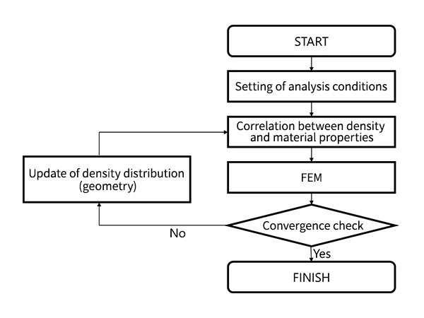 Fig. 3 Topology optimization process
Part design from Topology optimization results
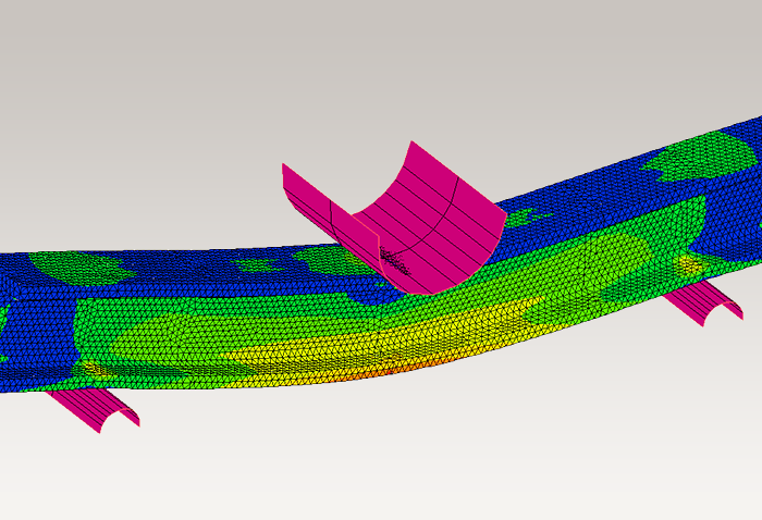
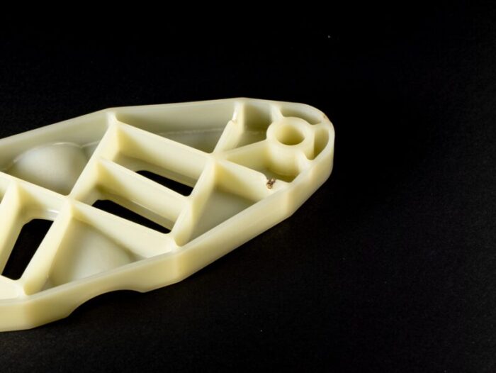
The optimal shape obtained through Topology optimization is simply an extraction of the material density distribution in the design space, so it cannot be used as a design shape as is. It is necessary to convert or create CAD data based on the results.
This is the most difficult process when applying Topology optimization to part design. Simply converting Topology optimization shape into CAD often results in a shape that cannot be manufactured. This process requires not only knowledge of CAE and Topology optimization, but also knowledge of actual manufacturability.
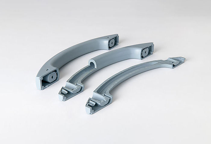
[Example of Topology optimization in practice]
Please refer to the following technical information page for practical examples of part design using Topology optimization.
Topology optimization | Asahi Kasei Engineering Plastics


Challenges of part design using Topology optimization
There are also challenges that must be overcome before implementing Topology optimization in part design.
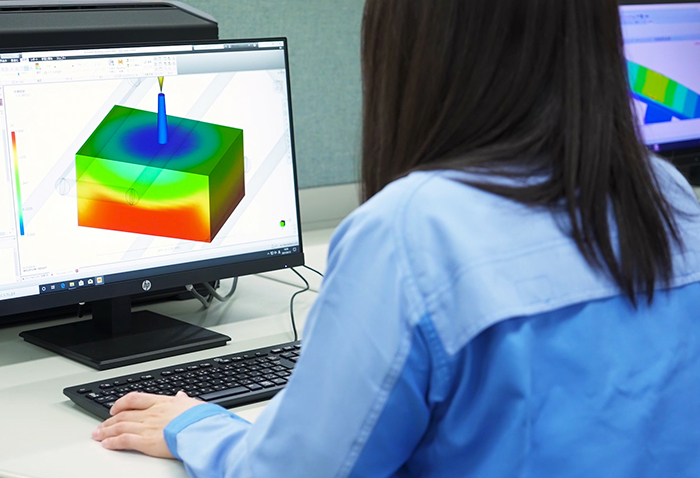
- Preparation of an environment for Topology optimization: Software capable of performing Topology optimization and the associated hardware are required. optimal process involves repeated numerical calculations using the finite-element method, so the hardware must be capable of withstanding this.
- Knowledge of Topology optimization: Knowledge is required to properly set the information required for Topology optimization described in the previous section.
- Translating Topology optimization results into product design: As mentioned in the previous section, this also requires knowledge of manufacturability, making it the most difficult of all these challenges.
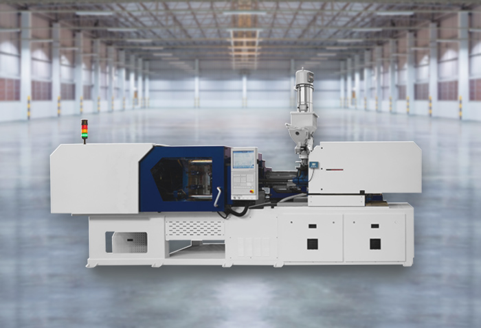
Asahi Kasei has the environment and knowledge to perform Topology optimization, as well as knowledge of injection molding of functional resins, and is therefore able to provide optimal designs for resin parts using Topology optimization.
If you are looking to design lighter, strength plastic parts, please feel free to contact us.
Summary
This paper introduced the basic concepts and methods of Topology optimization Topology optimization, a technology that enables lighter and strength structural designs by optimal the arrangement of materials in the design space.
When implementing this, it is important to properly set information such as the design space definition, material properties, load conditions, boundary conditions, objective functions, constraints, etc. In addition, when reflecting optimal results in actual product design, attention must be paid to practical issues such as manufacturability and conversion to CAD data.
By keeping these points in mind, Topology optimization can be effectively utilized to achieve higher performance part designs.
For more information about CAE, please contact us.
CAE Download Slides

CAE Services

CAE Application Case Study
Others


Related information