- TOP
- Basic Knowledge of CAE Analysis
- Part 8 Application to Gas-assisted injection molding
Series: Fundamentals of CAE Analysis for Plastic Product Design
Part 8 Application to Gas-assisted injection molding
In this issue of injection molding simulation using CAE, we will introduce an example of application to gas-assisted injection molding.
Update date:
2024.01.10
|Release date:
2024.01.10
Contents
| 1. What is Gas-assisted injection molding? |
| 2. What the simulation shows |
| 3. Optimal design using simulation |
| 4. Analysis Flow |
| 5. Summary |
What is Gas-assisted injection molding?
Gas-assisted injection molding is an injection molding method in which an assist gas such as nitrogen is injected immediately after resin is injected into the mold to increase the internal pressure of the molded product.
The advantage of gas injection molding is flow support for large molded parts where resin is difficult to flow. Since the internal pressure is increased by the gas, warpage and sink marks are prevented, and the dimensional stability of the molded product is improved. In addition, because low-temperature gas is injected, cooling time is shortened unless the product has extremely thick walls, thus reducing cycle time.
Gas injection creates a hollow structure in the molded product, which reduces the amount of resin in the molded product, resulting in weight reduction and cost cutting. However, the reduced amount of resin may reduce durability and strength. Strength and durability tests must be conducted to confirm that the product meets quality standards.
Gas-assisted injection molding was invented by Asahi Kasei in the 1970s and boomed in the 1990s as foreign manufacturers entered the market. It was used to produce frames for large-size TVs and panels for air conditioners, but as large-size molded products were shifted to overseas production, domestic demand for gas injection molding had declined. In recent years, however, the use of this molding method has been attracting attention again.


What the simulation shows
■ Flow behavior of resin and gas
In gas-assited injection molding, the process of injecting and filling the mold with resin is the same as normal injection molding. After that, however, the molding process involves gas injection and cooling, rather than a pressure holding process. We simulate the flow paths of the resin and gases through the mold to verify if they are properly molded.
■ Hollow Shape
By injecting gas into a molded product, the product becomes hollow. When gas is injected into thick-walled parts such as ribs, we simulate what kind of hollow shape (thick-walled shape) will be formed and confirm that the hollow shape is formed in the designed position.
■ Warpage
A characteristic of gas injection is that when gas is injected into a molded product, residual stress is reduced due to cooling caused by the gas passing through the molded product. This improves molding dimensional stability and eliminates warpage. We compare and verify the degree of improvement in warpage through warpage analysis.
■ Sink marks
As in the case of warping, the reduction of residual stress prevents sink marks. Perform a sink mark analysis and simulate the improved results. This is especially effective for large molded products.
Optimal design using simulation
In gas-assited injection molding, simulation of the effects of the gas can help to create a more effective and optimal design. It is important to understand the mechanism of gas injection and reflect it in the design.
■ Gas channels
A gas channel is a gas flow path. The hollow shape formed in the molded product is affected by this gas channel. How does the gas flow into the thin walls of the molded product? How gas flows into thin-walled areas, whether the thickness of the gas channel and the wall of the molded product is appropriate, and whether the weight of the molded product is appropriate are all checked and reflected in the design.
■ Polymer and gas entrances
Gases have a tendency to flow from areas of high pressure to areas of low pressure. The gas inlet must be positioned such that the gas flows properly into the molded product and the end of the flow path is at the lowest pressure. The gas inlet can be a nozzle or injected directly into the runner or mold.
■ Gas inflow timing
Gas injection starts at the end of resin injection, but residence time can also be set after the resin is filled.
■ Venting locations
A venting location can be specified at the end of the gas channel. Venting allows gas or resin to be released from the cavity. This allows gas to flow deeper into the molded product. Resin overflowing from the vent may need to be trimmed off after molding.
■ Mold temperature
Gas-assited injection molding injects cooled gas, which shortens the cooling time. Therefore, it is necessary to control the mold temperature by taking into account the amount of cooling by the gas. The optimal mold cooling time and temperature are set.


Analysis Flow
The flow of gas-assited injection analysis using CAE will be explained.
1. Setting the molding process (Gas-assited Injection)
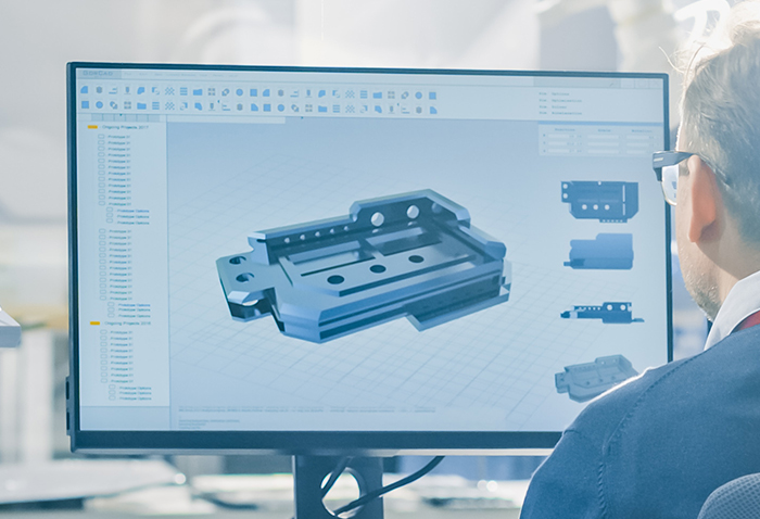
After generating a mesh for the molded product model (Fig. 1), the molding process (gas injection) is selected (Fig. 2). Selecting the appropriate molding process is critical for simulation accuracy.
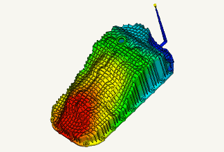
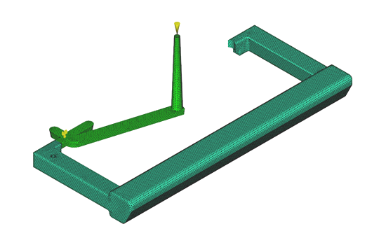 Fig. 1 Example of mesh model of molded product
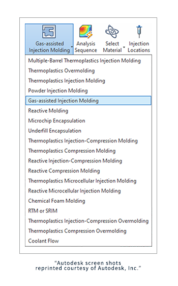 Fig. 2 Molding Process Setup Screen
2. Modeling gas channel
Filling and pressure retention analysis for gas injection requires modeling the area through which the gas passes (gas channel). It is important to accurately predict the gas flow in the analysis.
3. Generating mesh for the model
The gas channels are meshed according to their width and thickness ratios. After the mesh is generated and modified, an evaluation is made to determine if the mesh is suitable for the analysis.
4. Modeling of mold cooling channels
In gas-assited injection molding, cooled gas is injected into the melted resin, increasing cooling efficiency. Cooling tube modeling must take gas channels into account.
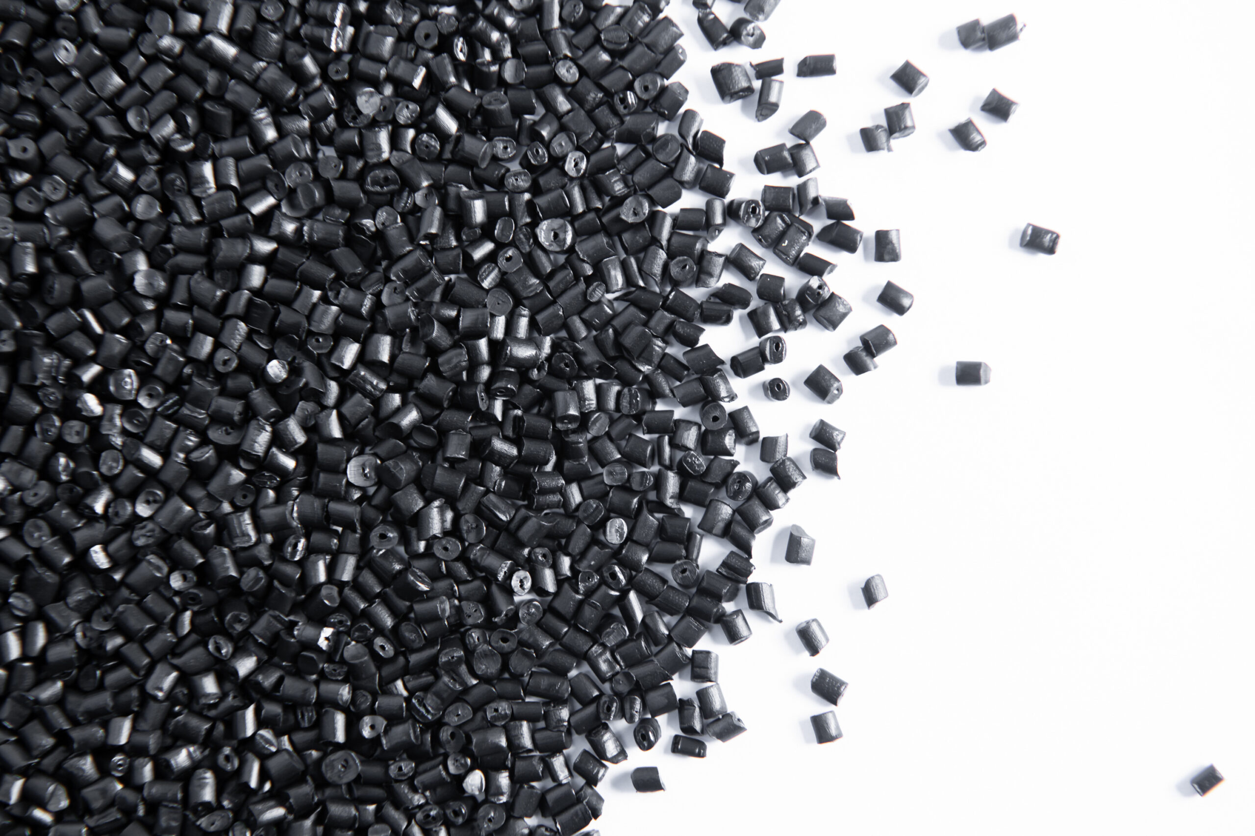
5. Material selection and injection location setting
Set the type of material to be used and the gate position.
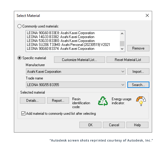 Fig.3 Material selection screen
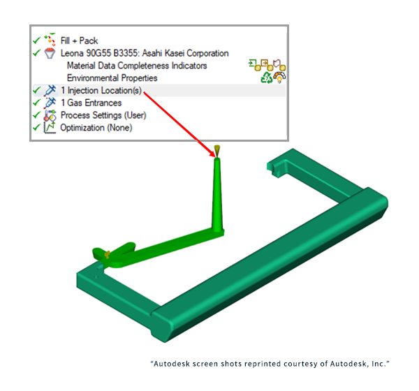 Fig.4 Gate position (injection location) setting screen
6. Gas entrances setting
Select whether gas is injected directly into the molded product or through the nozzle or runner of the molded product. If gas is injected directly into the molded product, select the entrance location. One or more gas entry points can be set.
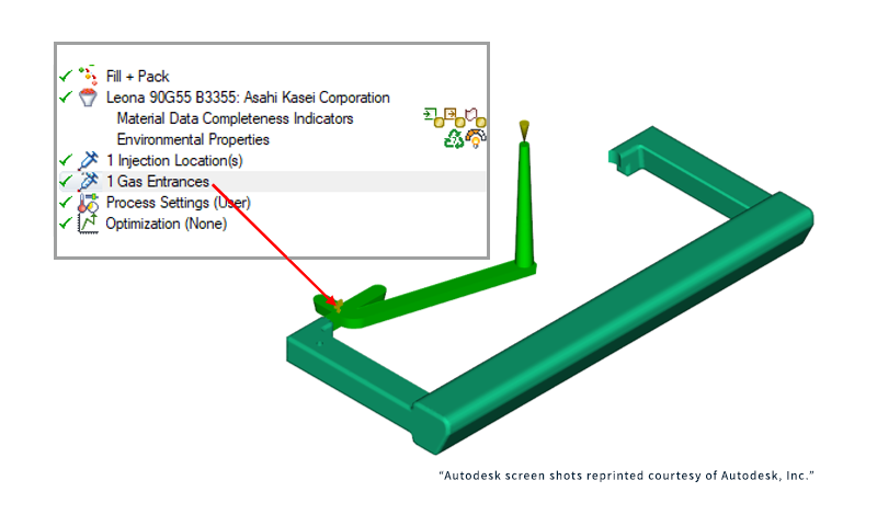 Fig.5 Gas entrances setting screen
7. Venting locations setting
To set the vent, set it at the end of the gas channel.
8. Process setting
・ Polymer injection condition setting
Set the conditions by taking into account the results of the simulation of the effects of gas injection from 1 to 7.
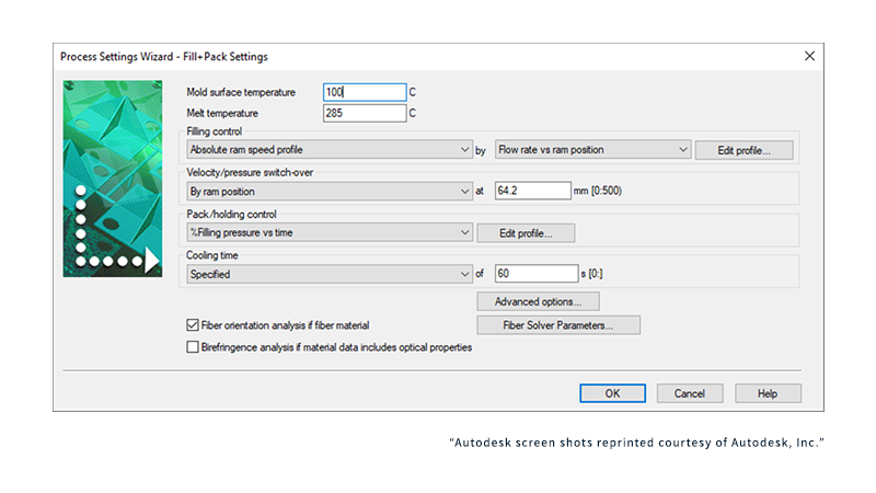 Fig.6 Polymer injection condition setting screen
・Gas-assisted injection condition setting
Gas is controlled by a pre-set volume or pressure. In the case of volume control, a pre-set volume of gas is injected, and the internal pressure of the gas is maintained during the pressure holding process to compensate for volume shrinkage. The internal pressure of the gas is then reduced.
In the case of pressure control, it can be step or profile controlled during the injection and holding pressure processes.
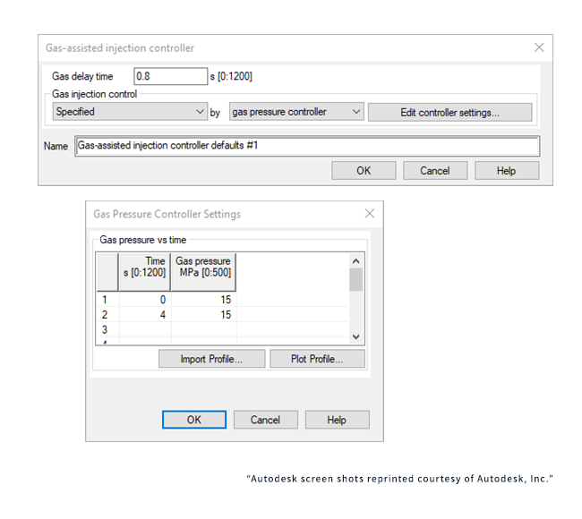 Fig.7 Gas-assisted injection condition setting screen
9. Mold cooling setting
Mold cooling temperature and time are set taking into account the effect of gas cooling efficiency. Effective cooling contributes to a significant reduction in molding cycle time.
10. Output evaluation
Based on the results of the analysis, we evaluate the results, reflect them in the design, and change the conditions.
Here are a example of gas injection analysis.
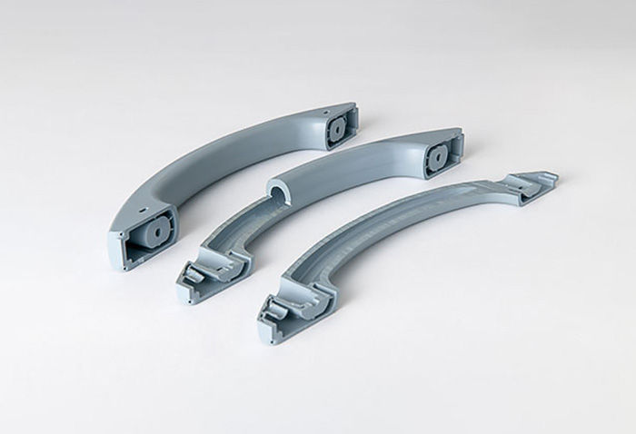
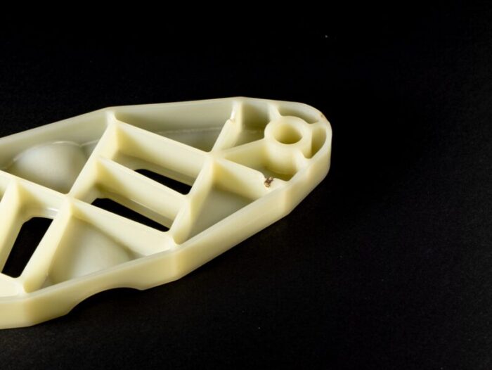
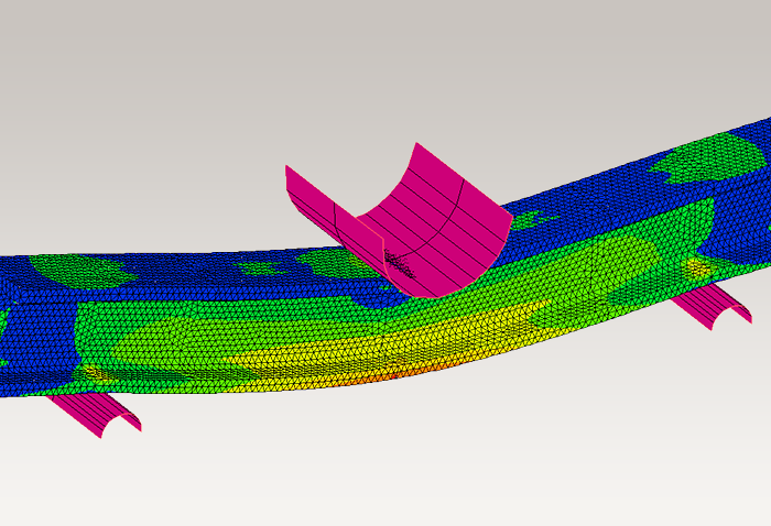
Gas-assited injection molding analysis was performed on a molded product with a handle shape.
The hollow shape of the actual molded product is compared with the simulation results.
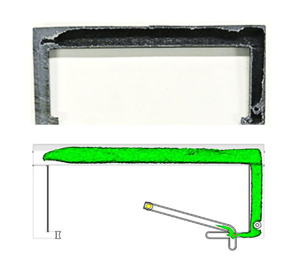 Fig.8 Comparison of hollow shape between actual and simulated molded products
There is no significant difference between the actual product and the analytical results, indicating that the simulation was performed properly.
Summary
Gas-assisted injection is a technique that has a large range of applications, not only for reducing defects in molded products, but also for its advantages such as weight reduction and cost savings. However, it is necessary to correctly understand the effect of gas injection on injection molding and to set the molding conditions. In order to maximize the effect of gas-assisted injection, CAE analysis should be utilized; proper condition setting in CAE analysis is important to obtain correct simulation results.
Next part, we will explain "Orientation in fiber reinforced plastics."


For more information about CAE, please contact us.
Easy to find on Google
Adding this site as a preferred source in Google search results will make it easier to find articles from Asahi Kasei engineering plastics Comprehensive Information Site.

Others

Related Information