- TOP
- Basic Knowledge of CAE Analysis
- Part 7: Predicting molding defects using injection molding analysis
Series: Fundamentals of CAE Analysis for Plastic Product Design
Part 7: Predicting molding defects using injection molding analysis
Injection molding analysis is a valuable tool for predicting molding defects at the design stage and taking countermeasures in advance.
In this part, we will introduce various types of molding defects and analysis evaluation items.
Update date:
2023.10.13
|Release date:
2023.10.03
Contents
Introduction
In the latter half of Part 6, we introduced that injection molding analysis can also predict molding defects such as sink marks, warpage, and weld lines. In Part 7, we will focus on molding defects and explain in more detail which evaluation items of injection molding analysis can be used for which defect phenomena.
Evaluation items in analysis and molding defects
Some molding defects can be identified and countermeasures developed in advance by conducting analysis at the design stage, while others cannot.Also, some defects can be inferred from the analysis results even if they are not included in the software evaluation items, and knowing these items will allow you to make better use of the analysis results.
The table below summarizes the molding failure phenomena and the analysis evaluation items that can be utilized for each.
Symbols in the "Analyzability" column indicate the following,
●:Direct output from simulation tools
〇:Can be evaluated by inferring from the evaluation items on the right.
▲:Currently being considered for development by software manufacturers
×:Difficult to predict from simulations
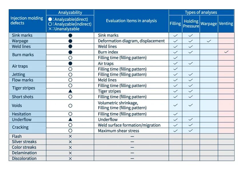 Fig. 1 Correspondence table between molding defects and evaluation items in injection molding analysis
Let me explain each of these molding defects.
Molding defects that can be directly output
■ Sink marks
Sink marks are molding defects that occur where the thickness of the moldings are different, especially on the front side where ribs, bosses, etc. stand on the back side. Since the surface of the molded product is indented, attention should be paid to this defect in products where appearance is important, such as in design. (If the sink marks are large, dimensional accuracy may be an issue.
Sink marks are caused by differences in shrinkage rates during thermal contraction during cooling.The location and depth of sinkholes can be simulated and evaluated from Filling and Holding Pressure analysis.
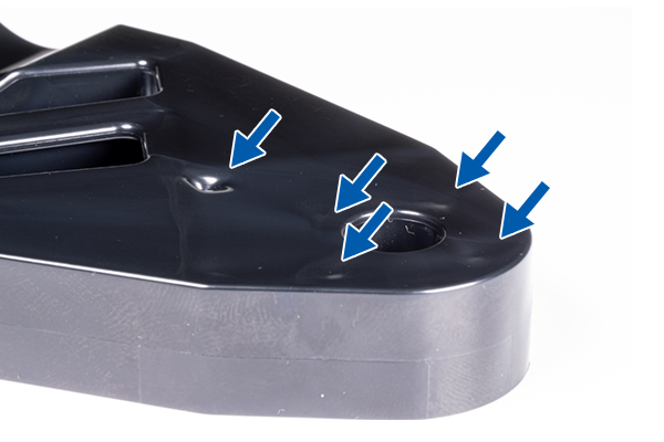 Fig. 2 Example of sink marks
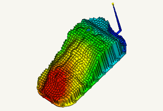
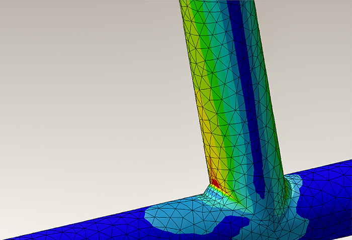
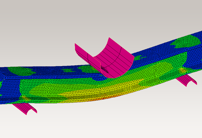
■ Warpage
This is a phenomenon in which molded products warp due to shrinkage differences between thin-walled and thick-walled sections, shrinkage differences during cooling, orientation of fiber compounding materials, residual stress, and other factors. This phenomenon can occur after a long period of time after molding, so care must be taken to avoid it. In addition to molding defects, it can also result in dimensional defects and poor fitting of parts that require assembly.
Warpage analysis can be used to simulate deformation diagrams and displacements.
■ Weld lines
Weld lines are molding defects that appear as lines at the confluence of molten resin filled into the molded product. The thin, scratch-like appearance of the weld lines can result in molding defects, and the strength of the product is reduced where weld lines occur, which can lead to breakage.
Filling analysis can be used to predict where weld lines will occur.Although it is difficult to completely eliminate weld lines, measures can be taken to move them to locations where they are less visible or make them thinner by adjusting gate positions, etc.
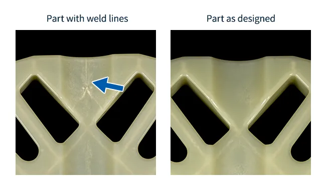 Fig. 3 Example of weld lines
■ Burn marks
Burn marks are molding defect in which a portion of the molded product is burned and carbonized black. This is also called gas burning or gas. This occurs when air and volatile gases in the resin material are trapped inside the mold during molding and compressed to a high temperature, causing the resin to burn.
Venting analysis will generate burn index results.This is a very challenging simulation because it requires inputting gas release information in the mold without omission.
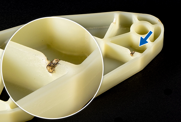 Fig. 4 Example of burn marks
■ Air traps
When multiple molten resins merge, air and gases are trapped in an air trap. This can result in air bubbles, which can cause small holes on the surface of the molded product, as well as insufficient strength. In severe cases, burns may occur.
The flow path tends to be unbalanced or the flow is uneven, and the location of the flow path can be predicted by checking the filling time results.


Molding defects that can be inferred from other evaluation items
■ Jetting
Jetting is a molding defect in which the resin injected into the mold snakes and flows in an overlapping pattern on the surface of the molded product. Jetting tends to occur around the gate area and can cause lack of strength.
Jetting can be predicted by checking the meandering flow of resin in the filling area results of the Filling analysis.
■ Flow marks
Flow marks are patterns of resin flow that occur during injection. There are various types of flow marks, but a concentric ripple-like pattern appearing around the gate is a molding defect. Low mold temperatures, resin temperatures, and insufficient pressure retention are causes of flow marks.
It can be predicted indirectly from the meld lines in the Filling analysis.A meld line is a line where the meeting angle is larger than the weld line when the resin merges. This means that flow marks may occur at this point.
■ Tiger stripes
Tiger stripes are repeated pattern of low and high gloss areas alternating on the surface of a molded product. Compared to simple flow marks, flow marks are caused by complex flow, so experience is required to verify the flow pattern.
Development is underway by software manufacturers so that analysis tools can be shown as analysis results.
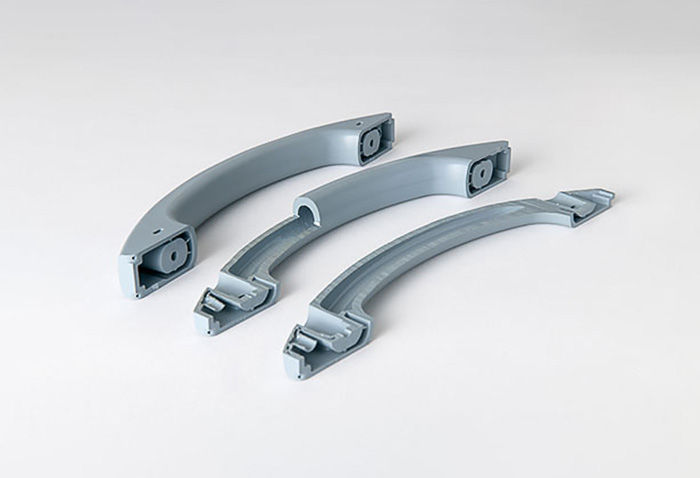
■ Short shots
Short shots are molding defect where the molten resin does not completely fill the mold up to the top of the mold. This is a serious molding defect that results in shape failure.
Short shots can be predicted by checking that the flow path is completely filled with Filling analysis.
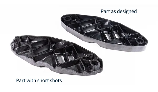 Fig.5 Example of short shots
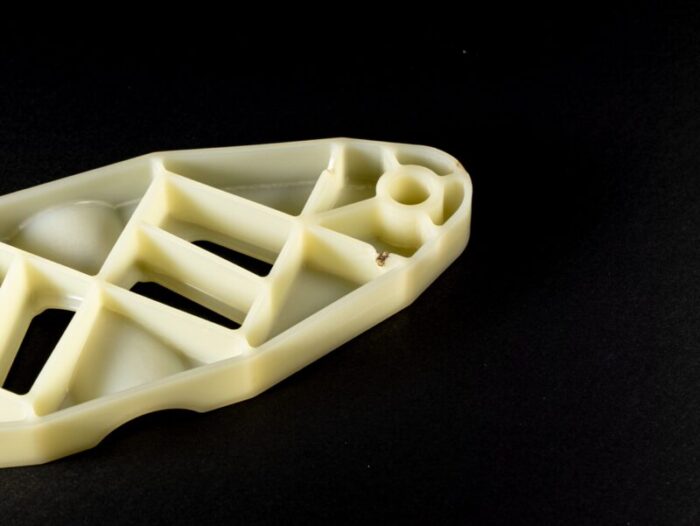
■ Voids
This is a molding defect where voids (bubbles) are generated in the molded product. If the molded product is transparent, this is a molding defect. It can also cause cracking and lack of strength due to stress concentration. Bubbles occur when resin is attracted to a surface that is easy to cool during the cooling process. Bubbles are vacuum bubbles immediately after they occur, but as time passes, air can enter. Bubbles tend to form inside thick-walled areas.
It can be simulated indirectly from the volumetric shrinkage, the filling pattern and filling time of the Filling analysis .Since the cause of occurrence is similar to sink marks, the basic measures are the same as those for sink marks.
■ Hesitation
Hesitation is a condition in which resin does not flow into thin-walled parts because thick-walled parts, where molten resin flows easily, are filled first when resin is injected. Hesitation can cause molding defects such as short shots and sink marks, as well as variations in appearance quality.
Fill time results can be checked to see if hesitation may be occurring.
■ Underflow
When molten resin merges from two directions, one resin flows backward, which is called underflow. Re-melting of the already solidified resin can cause problems with the appearance and strength of the molded product.
An animation of the filling pattern allows you to check for flow direction reversal at the flow front confluence. Currently, this is predicted by checking through the Filling pattern animation, but it is being developed by software manufacturers so that it can be confirmed as an analysis result.
■ Cracking
This is a phenomenon in which a molded product breaks or cracks. It may occur after a long period of time after molding.
If cracking is caused by insufficient strength at the weld line, it can be predicted by checking the thickness direction of the weld line (weld surface) in 3D. If cracking is caused by residual stress in the molded product, it can be predicted by checking the maximum shear stress in the direction of the wall thickness.
Difficult-to-predict molding defects from simulations
■ Flash
This is a molding defect in which resin is pushed out through gaps in the mating surfaces of the mold, resulting in a thin film of molding. Additional processes such as manual removal are required.
Insufficient mold clamping force, too much pressure, etc. can cause this problem, but it is often caused by physical problems with the mold and is difficult to predict by simulation.
■ Silver streaks
A molding defect in which striations or patterns appear on the surface of the molded product.
It is caused by air, volatile gases, and moisture contained in resin materials. Because it is derived from resin, it is difficult to predict by simulation.
■ Color streaks
Color streaks are characterized by the appearance of a stripe-like pattern of uneven resin color on the surface of the molded product.
It is difficult to predict by simulation because it is often caused by the coloring material of the resin material.
■ Delamination
Delamination is a molding defect in which a film-like layer forms on the molded product and then peels off. This is a molding defect or shape defect.
This can be caused by incompatible resin contamination, etc. It is difficult to predict by simulation.
■ Discoloration
Discoloration is a molding defect in which the molded product changes from the original resin color.
Molding materials are often the cause, such as poor dispersion of colorants or yellowing due to thermal degradation of the resin, which are difficult to predict by simulation.
Summary
It is difficult to solve all molding defects only at the molding site, and it is required that as many countermeasures as possible be taken at the design stage.To this end, designers must also know the characteristics of resins and molding defects, and understand the causes and principles of their occurrence.
In addition, some molding defects can be identified and countermeasures developed in advance by conducting analysis at the design stage, while others cannot.Some molding defects can be inferred from the analysis results even if they are not in the software evaluation items, so knowing these things will help you make better use of the analysis results.
If you have any questions about molding defect countermeasures using injection molding analysis, please feel free to " Contact Us ".
Next part: "Application to Gas-assisted Injection Molding".


For more information about CAE, please contact us.
Easy to find on Google
Adding this site as a preferred source in Google search results will make it easier to find articles from Asahi Kasei engineering plastics Comprehensive Information Site.

Others


Related Information