- TOP
- Basic Knowledge of CAE Analysis
- 第1回 構造解析をはじめて体験してみよう
Hands-on Series for Simplified Structural Analysis
Part 1: Getting Started with Structural Analysis
This introductory guide walks you through the basics of structural analysis, from fundamental concepts to the analysis workflow, using a simple web-based application. No prior expertise is required. You can intuitively grasp deformation and stress behavior.
Update date:
2026.06.11
|Release date:
2026.06.11
Contents
| 1. What is structural analysis? |
| 2. Flowchart of structural analysis |
| 3. Try the workflow with the Simple Structural Analysis Tool |
1. What is structural analysis?
Structural analysis is a method used to evaluate how structures respond to loads, including stress, deformation, and displacement.
- Will it break?
- Is it bending too much?
These can be evaluated on a computer before physical prototyping.
[Practical Examples]
- When placing heavy objects on a shelf
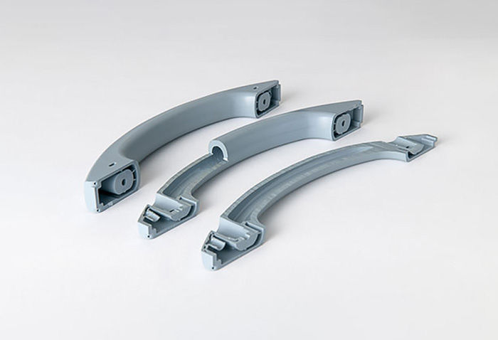
→How much will it bend? Will it break? - When supporting parts with a resin bracket
→ Will stress concentrate and cause damage? - When replacing metal with resin
→Is strength sufficient? How thick does it need to be?
Structural analysis allows us to address these questions not only through intuition and experience, but also by visualizing numerical data and physical indicators.
2. Flowchart of structural analysis
A typical structural analysis process consists of the following steps:
- Create or import geometry
Create the geometry of the part to be analyzed.
The CAD model is then divided into smaller elements (mesh generation) for analysis. - Assign material properties
Set the material's modulus of elasticity, Poisson's ratio, etc. - Define loads
Specify where, how much force, and in what direction loads are applied. - Define boundary conditions
Specify fixed regions (areas that do not move). - Run the analysis
- Evaluate the results
Determine whether the design is safe based on deformation and stress distribution.
While full-fledged CAE requires specialized knowledge to make appropriate settings at each step, simplified structural analysis allows you to go through this process in a simplified way. By following these steps, you can easily perform a basic structural analysis.
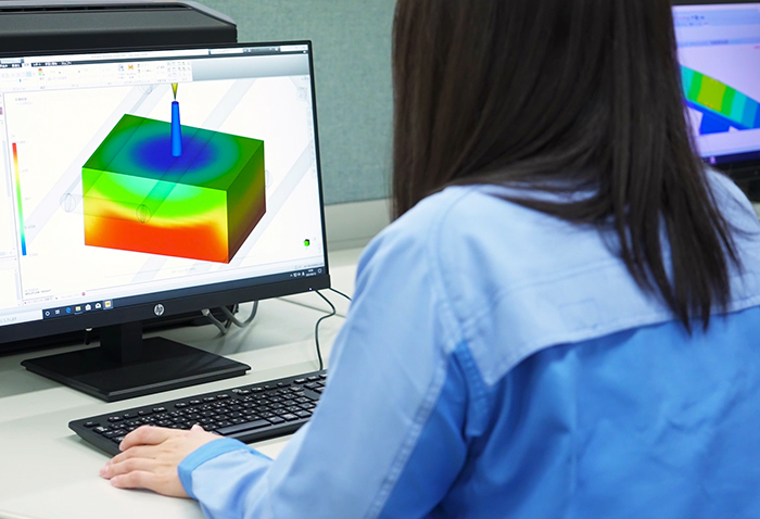
3. Explore the workflow with the Simple Structural Analysis Tool
Now, let’s use the Simple Structural Analysis web app to go through the process.
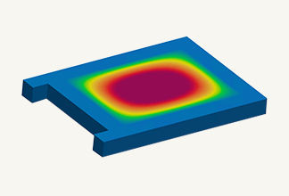
Step 1: Select a sample model
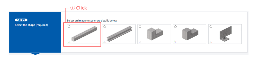
- This tool uses a predefined model.
- Select the leftmost model, "Bending Analysis of a Cantilever Beam". (①)
→ You can start immediately without creating geometry.
Step 2: Enter material properties
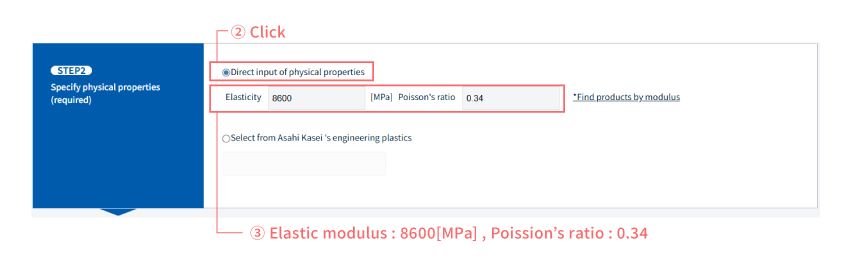
- Select "Direct input of physical properties" to enter the values directly. (②)
- Enter an elastic modulus of 8600 MPa and a Poisson's ratio of 0.34. (③)
No complicated parameter settings are required; you can perform simple structural analysis by entering basic material property values.
Step 3: Define load conditions
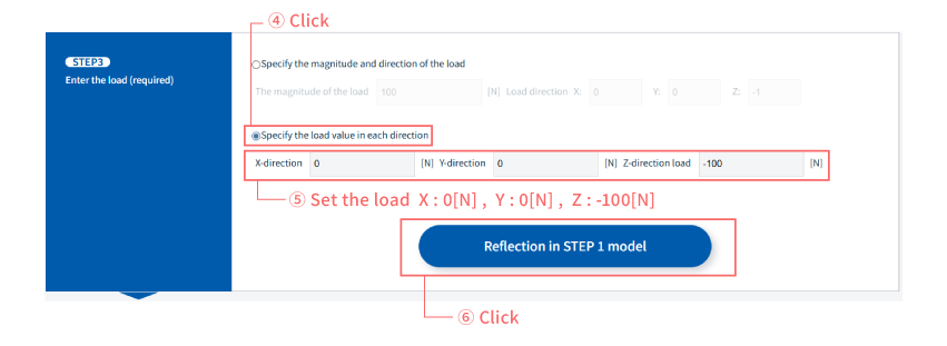
- Select "Specify load values for each direction". (④)
- Set the loads for each direction. In this case, we will set them as follows: X direction: 0[N] Y direction: 0[N] Z direction: -100[N]. (⑤)
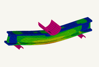
- Click "Apply to STEP 1 Model" to visualize the analysis settings. (⑥)
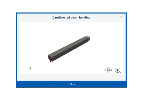
- The red arrows indicate the direction of the load, and the blue marks indicate the points of fixation. In this simplified structural analysis, the fixing points are predetermined, but in reality, you would set the fixing conditions yourself.
- You can rotate and zoom using the mouse drag or wheel. Click "Close" when you're finished.
Step 4: Execute analysis
- Enter the information in STEP 4 and click the "Start Analysis" button.
- The calculation will be completed in less than one minute.
→ This simplified structural analysis does not require specialized CAE software or a high-performance PC.
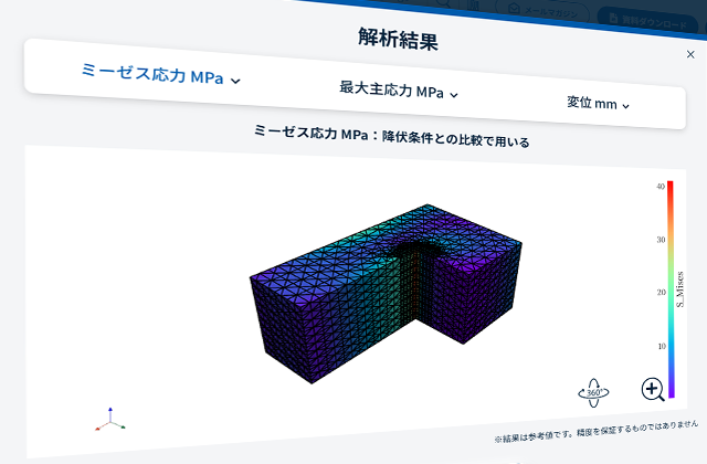
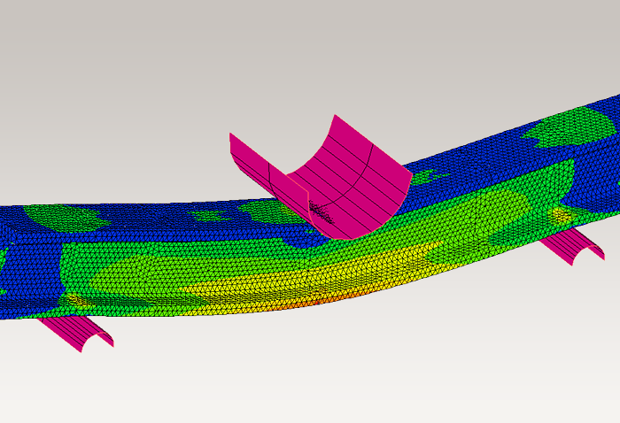
Step 5: Check the results
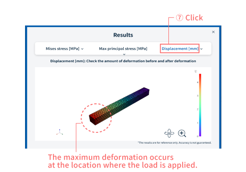
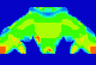
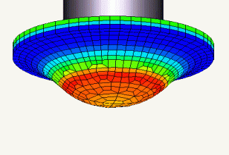
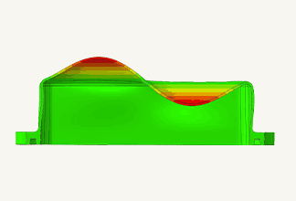
- Click "Displacement" at the top of the screen. (⑦)
- Displacement (deformation) is visualized using a color scale.
- In this problem, we can see that the part where the load is applied experiences the greatest displacement and deformation.
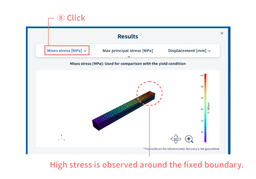
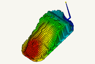
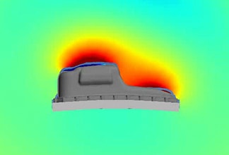
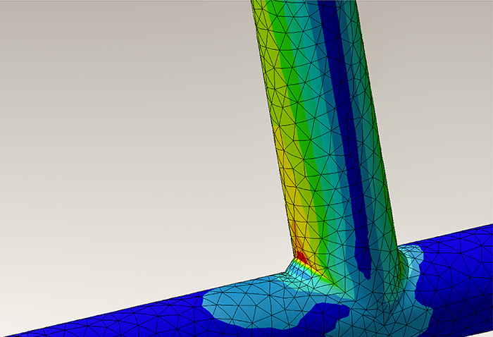
- Next, click on "Mises stress". (⑧).
- The stress distribution is shown in colors. Stress shows how much load is applied to the material, and higher stress increases the risk of failure.,
- This analysis reveals that high stress is occurring in the fixed portion.
You can see at a glance things like, "This part looks weak," "There's plenty of room here," and "How much will it deform?"
Step 6: Try comparing with different conditions.
Now, let's try changing the analysis conditions to see what happens.
- What happens when the load is increased?
- How does the stress change when the material properties are altered?
→ Structural analysis is most effective when used for comparison.
By changing the conditions and comparing the results, you gain a clearer direction for your design.
For more information about CAE, please contact us.
Easy to find on Google
Adding this site as a preferred source in Google search results will make it easier to find articles from Asahi Kasei engineering plastics Comprehensive Information Site.

Others


Related Information